
APFs are one of the fastest growing technologies for solving power quality problems and meeting grid code and energy efficiency requirements for a wide range of segments and applications.
Most installations nowadays are exposed to a large number of power quality problems and challenges to comply with grid code and energy efficiency requirements as they are not designed to support nonlinear, non-balanced and variable loads and generators that make up a large percentage of modern electric power systems.
These problems and challenges originate from equipment like variable speed drives (VSD), welding machines, transformers, furnaces, lighting, double conversion UPS systems, highly dynamic loads, single-phase loads, battery chargers, railway electrification systems, fossil fuel generators and renewable generation sources, to name a few. Events like capacitor switching (from existing capacitor banks or passive harmonic filters), auto-reclose operations of transmission and distribution lines or the starting of large motors also contribute to these problems and challenges.
Active power filters (APF) are one of the fastest growing power electronics technologies for solving power quality problems and meeting grid code and energy efficiency requirements for a wide range of segments and applications. Modern APFs can be controlled to act as current or voltage generators. They can be connected in parallel or in series with the electric power system. The APFs connected in parallel are called shunt APFs or current-fed APFs and they are the most widely used APFs nowadays. The APFs connected in series are also called voltage-fed APFs. The voltage source converter (VSC) based shunt APF is by far the most common type due to its well-known topology, reasonable costs and straight forward installation procedure.
1. Shunt active power filters
Conventional solutions like capacitor banks, shunt reactors and passive harmonic filters, consisting of inductance, capacitance and resistance components, do not always respond correctly to the required dynamics of modern electric power systems. Although simple in construction and depending on the application sometimes highly cost-effective, they inherit several shortcomings.
Shunt APFs were developed and commercialized as an economical solution to deal with all these shortcomings offering a performance independent of the electric power system properties while being able to comply with the real time requirements of modern loads and generators.
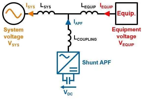
Figure 1: Basic schema of a shunt APF.
Shunt APFs are devices that behave as a controlled current source providing any kind of current waveform in real time. They are equipped with an energy storage element, an IGBT bridge and a control system, which enable the device to inject the required current to the electric power system. They can be installed to any point of the system (low or high voltage) in parallel with the equipment that cause problems or need to comply with certain requirements. Their operation is independent from network impedance, curve form of the current to be compensated and the quality of the supply voltage.
Over the years, the design of shunt APFs has been tailored to deliver specific functionalities. They are able to compensate current-based distortions such as current harmonics and current unbalances, and voltage-based distortions such as voltage harmonics, voltage fluctuations, voltage variations and voltage unbalances.
They can also support the development of clean energy by power factor correction and the reduction of the energy losses in the electric power system.
Customized APF solutions that can be found currently in the market include active harmonic filters (AHF), static var generators (SVG), active load balancers (ALB) and two types of special designs, hybrid var compensators (HVC) and low harmonic drives (LHD).
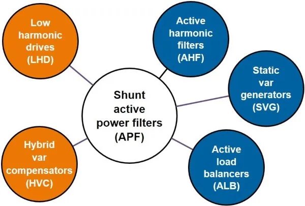
Figure 2: Types of shunt APFs.
2. Specifying or purchasing a shunt active power filter
There are several factors that should be carefully considered when specifying or purchasing a shunt APF for a low or high voltage application. The following factors are some of the most important.
Functions
In principle, a shunt APF can correct a wide variety of power quality problems such as harmonic distortion (of any phase sequence), fundamental-frequency reactive power (non-unity displacement factor), negative sequence fundamental components (unbalance components), zero-sequence fundamental components (neutral line current) and voltage fluctuations.
A shunt APF can also support the development of clean energy by power factor correction and the reduction of the energy losses in the electric power system.
It is tempting to consider that all of the various power quality problems and grid code requirements can be dealt with by simply adding control functions to the basic shunt APF inverter and control system. However, each corrective action contributes to the volt-ampere rating of the inverter and hence to the cost of the device. Compensation of unbalance and voltage fluctuations also have implications for the DC-side energy store since the energy flows represented by peaks in the instantaneous power can be large.
It is important to study in detail the application and clearly define the functions needed from the APF to take care of the problems or requirements as requested by the end user. Depending on the functions needed, the right type of shunt APF can be specified or selected.
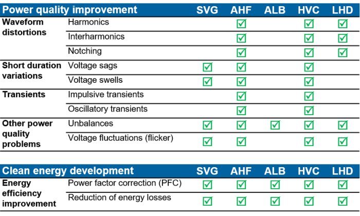
Figure 3: Typical functions that APFs can provide.
Response time
Some power quality phenomena occur extremely fast and some grid code and energy efficiency requirements require a real time response. It is very important to evaluate both, the APF’s reaction time and the overall response time, to make sure that the device fulfils the needs of the application.
The speed of response plays a major role in deciding the control philosophy to implement in the required APF. In general, the cost of any particular APF is related to the speed of response implemented.
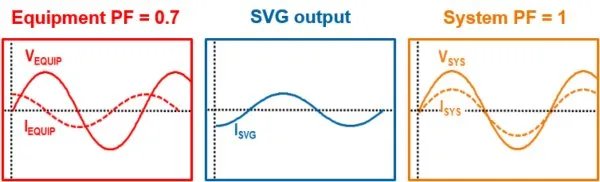
Figure 4: Typical instantaneous response of an SVG.
Voltage range
Shunt APFs are offered in a range of voltages, most common is 200 V up to 690 V, as they are built using low voltage IGBT switches. Some manufacturers offer devices that can be connected directly to the electric power system within this voltage range.
Some other manufacturers design APFs for one certain voltage level (usually 400 V) and then they connect the APF to the 200-690 V electric power system by using an step-down or step-up transformer. This approach increases the size, costs and losses of the whole solution.
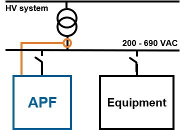
Figure 5: Typical direct low voltage connection for an APF.
It is possible to connect APFs to high voltage (over 1 kV) systems using a suitable step-up transformer. In these cases, the current transformers providing the current signals are located near the high voltage equipment that needs compensation.
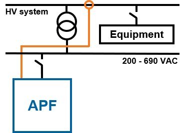
Figure 6: Typical high voltage connection for an APF.
When using transformers for the connection of the APFs, these transformers should be studied carefully during the design phase of the project. Step-up or step-down transformers could reduce compensation performance due to increased impedance in between the APF and the electric power system.
Inverter topology
Most modern shunt APFs are built on the latest VSC topology, 3-level neutral-point clamped (NPC) inverter topology, which brings several benefits compared to APFs built on the conventional 2-level topology.
In 3-level topology, the switching frequency and voltage stress are distributed among the IGBT switches leading to a better spectral performance of the output voltage. Reduced stress extends lifetime of the power electronics. Higher efficiency, smaller output current ripple, lower losses, lower noise levels and a more compact design with smaller layout are also achieved. These advantages make the overall total cost of ownership (TCO) much lower.
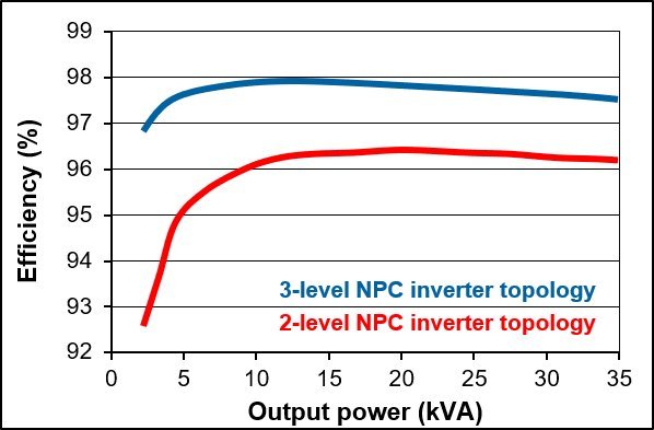
Figure 7: Efficiency comparison between 3-level NPC inverter topology and 2-level.
Internet-enabled technologies
Shunt APFs using industrial internet of things (IIoT) technologies can accurately and consistently capture and communicate data in real time. The adoption of the IIoT by APFs is being enabled by the improved availability and affordability of sensors and processors. The IIoT allow the incorporation of machine learning and big data technology into the devices.
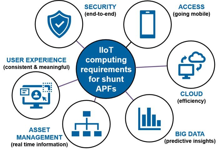
Figure 8: IIoT computing requirements for shunt APFs.
Some manufacturers offer the possibility to connect all APFs on a site through a web-based architecture. An operator can then have an overview of the status of all connected APFs and log them. This enables the possibility to log events that could have caused production disturbances and monitor individual APFs.
There is an increasing market demand for smart devices and wireless connectivity technology for industrial equipment. Many APFs in the market offer the possibility of remote asset connectivity, big data processing and analytics by using IIoT software platforms. This can improve the operational efficiency of installations (e.g., improved uptime and asset utilization) through predictive maintenance and remote management.
Rated output
APFs offer an instantaneous, continuous, stepless and seamless output that is not affected by grid voltage fluctuation. Their capacity and rated output can be selected to be exactly what the application requires.
This is a big difference compared with conventional solutions like capacitor banks, shunt reactors or passive harmonic filters that are usually oversized to better adjust to changing demands of the equipment that has to be compensated. Another disadvantage of these conventional solutions is that they continuously over and undercompensate the electric power system as their output is injected into the system in steps of a certain size.
Selecting an APF that delivers the exact output demanded by the application helps reducing the costs of the whole solution. In the market can be found modular devices with an output as small as +/-30 kvar for SVGs or 25 A for AHFs to adjust to the needs of modern buildings or water irrigation systems for example. There can also be found modular devices with an output as large as +/-150 kvar for SVGs or 200 A for AHFs to adjust to the needs of modern manufacturing plants or renewable generation plants for example.
Controller and redundancy
The increased sensitivity of most facilities and processes to power quality problems turns the availability of electric power with good quality a crucial factor for the development of the electric power system. Ensuring complete system redundancy is a major issue in many applications nowadays, especially for critical process industries and critical process facilities.
A very safe design that ensures system redundancy is to use modular type APFs with an independent controller design (master/master arrangement). With this design, if any module of the APF fails, the rest will continue in operation without damaging equipment or interrupting processes.
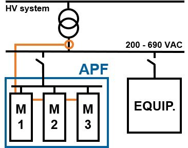
Figure 9: Redundant modular type of shunt APF.
Electromagnetic compatibility (EMC)
In some countries there are strict guidelines regarding EMC. To be sure that the APF is not causing any interference it must be fitted with a properly designed EMC filter. Typical EMC standards required for APFs are IEC 61000-6-2 (immunity) and IEC 61000-6-4 (emission).
Harmonic compensation capacity
Harmonics can be seen in the odd and even harmonic orders. Common compensation capacity for APFs in the market is being able to mitigate up to the 50th harmonic order (odd and even). Sometimes there is a claim by some manufacturers of being able to mitigate the 51st harmonic order or above, which has little value as these harmonic orders do not cause problems or usually appear in electric power systems.
An important feature that APFs can offer is the possibility of selecting which harmonic order to compensate. For some devices, it is possible to select the whole harmonic spectrum (2nd to 50th, odd and even), but for some others only few harmonic orders can be selected. Depending on the application, the capacity to compensate a certain harmonic order is a critical issue affecting the performance of the whole system.
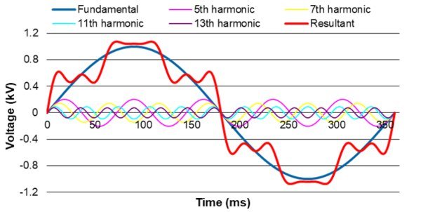
Figure 10: Harmonics waveform.
Derating according to harmonic order
The rating of an APF is usually defined at nominal load (at 50/60 Hz). As the APF works further up the harmonics its capacity compared to nominal starts to derate. For example, a derating of 50% at the 13th harmonic order means that a APF with a current output rating of 100 A has only the capability to compensate 50 A at the 13th harmonic order.
Derating is a matter of how robustly the APF is designed. This capability is more dependent on the change rate of the current than just the frequency and magnitude of the current (all different frequencies, their magnitude and their phase have an effect). Because of this, a derating curve cannot show the capability of a certain APF. The only way to verify the real compensating capability of a device is to check its di/dt capacity. This compensating capability is clearly better in 3-level NPC inverter topology APFs compared to 2-level devices.
Interharmonics
Interharmonics are usually caused by synchronisation issues or the operation of equipment like cycloconverters, induction furnaces or some wind turbine generators. If the installation includes sources of interharmonics, the manufacturer should be consulted as not all APFs can deal with them.
Mounting arrangement
Most shunt APF suppliers offer several installation alternatives:
Cubicle type devices: A full rating APF is built into a cabinet that is fixed to the ground.Wall mounted devices: A full rating APF is built into a light and compact cabinet that is fixed to a wall.Rack-mounted devices: One or several APF racks mounted in an specially designed cabinet.Loose module devices: One or several APF modules can be installed inside an existing or new cubicle.A modular APF design allows end users to adapt to potential changes in future power quality and energy efficiency improvement needs or grid code requirements. Modular design means that it is possible to add easily extra capacity to the APF’s capacity within the existing configuration, saving both costs and space.
Losses
Depending on their design and topology, APFs can have higher or lower losses. Checking the losses is important as low losses will reduce the life cycle cost (LCC) on the investment.
Usually, APFs have about 2-3% losses (depending on rated power). APFs built on 3-level NPC inverter topology have lower losses than 2-level ones. Depending on user profile, losses mean a potential for considerable financial savings if the LCC is calculated over a few years period.
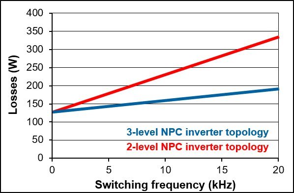
Figure 11: Losses comparison between 3-level NPC inverter topology and 2-level.
HMI and commissioning software
There are different HMI setups for APFs. Some offer a very simple interface while others have a built-in power quality analyser to calculate the required compensation that includes graphs showing the current and voltage waveforms and many extra functions in different languages. A great added value for any HMI is the possibility of connection to any IIoT software platform.
Commissioning and service of APFs without proper tools can be time consuming. Some suppliers provide software for this. Minimum required functionality should be that the system performs a self-check of voltage and CT phase order, CT polarity check, self-diagnosis and self-calibration. Such features will find installation errors before they can cause problems and will shorten the commissioning time. If the APF does not have this type of software the commissioning becomes more complex and might require external support adding to the system costs.
Built-in protection functions
Modern APFs have several built-in protection functions to ensure safe and reliable operation during abnormal system conditions. Some of the most common built-in protection functions are:
Internal short circuit protection.RMS and peak value overcurrent.AC-system and DC electrolytic capacitor over and undervoltage.Ripple circuit overloading and ripple circuit failure.IGBT switches and enclosure overtemperature.Control of detuned capacitor banks
Very often APFs are installed at sites together with existing or new contactor or thyristor switched detuned capacitor banks. Some APF suppliers offer the possibility to control the steps of these banks directly from the APF’s control system through dedicated digital outputs in the APF. By doing this it is possible to use the comprehensive power quality monitoring and reporting features of APFs to accurately monitor all the parameters of the installation and manage the total power quality improvement needs.
Together with an optimal system integration, this feature brings efficient operation, cost savings on the control system, and the possibility to build a hybrid var compensator (HVC) using an existing or a new detuned capacitor bank.

Figure 12: HVC connection diagram
About the author
Pedro Esteban is the Director for Asia-Pacific for Merus Power Plc. He holds since 2002 a broad global experience in sustainable energy innovation and transition including renewable energy, power electronics solutions, energy storage, microgrids and their Smart Grid integration. He has been a leading expert in several marketing, strategic planning, business development and communications positions at Areva T D, Alstom Grid and General Electric. He is based since 2012 in Singapore.
To connect with Pedro, you may reach him at pedro.esteban@meruspower.com or at linkedin.com/in/pedrojavieresteban.