
Amid the increasing adoption of mobile, IoT and smart devices, ensuring data integrity and safety at all conditions is becoming an important concern.
With wide adoption of mobile, Internet of Things (IoT) and smart devices, ensuring data integrity and safety at all conditions is becoming an important concern. These devices normally have a main power source which support the normal operation. When main power source is lost unexpectedly, the device is required to keep all or part of the function alive for certain time to perform necessary functions like data backup and status report. Some systems also need to keep low power circuitry alive for days or weeks. To achieve this goal, a backup power is needed in these devices other than the main power source.
For example, more drivers are installing car dash cameras for driving safety concern. In this application, the camera will get main power from USB port in the car. When the car is turned off or involved in an accident, the input power could be lost. Under these circumstances, there is a need for the camera to process data, save data or even keep recording video. Also, it is expected that the camera could keep a real time clock alive even after the car is not used for days or even weeks. To satisfy this need, Li-ion battery can be used as backup power inside the camera. One problem with Li-ion battery is the limited operating temperature range. In a hot summer day, with direct sun light, camera temperature could reach over 70 ℃ which exceeds the safety operating temperature range for Li-ion battery.
Another example is the smart electricity meter application. For this application, the meter gets main power from AC power line. When AC power is lost, the smart meter must have sufficient energy storage to energize the AMI (Advanced Metering Infrastructure) network for a period long enough that all other smart meters can report their status to the utility’s central office. Moreover, for safety and security concerns, meters are normally sealed and installed outside with operating temperature vary from -40ºC to 70ºC. This application calls for an energy storage device with high energy storage capacity, wide temperature range, long lifetime and maintenance-free operation.
Similar need happens in many other applications, like IoT devices with energy harvesting and energy storage, telecommunication equipment, industrial equipment, or other electrical equipment. All these applications call for an energy storage solution with wide temperature range, high power density, low leakage current and long operating life.
Energy Storage Devices
Capacitor, as a basic circuit element, can support wide range of voltage. It provides high instant power, almost unlimited charge, and discharge cycle. But due to its low energy density, its use for backup power is limited. To hold enough energy for the need of backup power, tens or even hundreds of capacitors are needed. This will increase the solution cost and size.
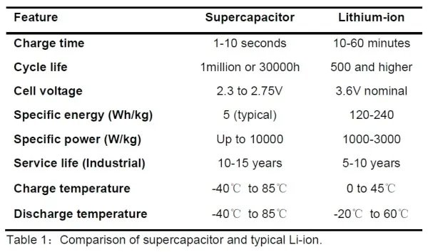
Lithium-ion batteries can store large amount of charge. It has been used in wide range of mobile applications as primary power source. The main problem with Lithium battery is low cycle life, limited operating temperature range and low output power capability. Normal charge temperature is limited to 0 to 45°C while discharge temperature is limited to -20°C to 60°C. This will limit its use in many applications as shown above. A Li-ion battery has a lifetime of only about 500 charge cycle and needs complex charging circuit to ensure safe operation.
Source: Battery University
Supercapacitor or EDLC (Electric Double Layer Capacitor) has a lower energy density compared with battery, but is 10 times higher than capacitors. It has much higher power density compared with batteries, which is a critical requirement for applications that need high instant power. It can operate with wide temperature range from -40 to 85°C. Supercapacitor has very long-life cycle of more than 500,000 cycles, which enables maintenance-free operation. Charging and discharging of supercapacitor behave very much like a capacitor. This greatly simplifies the charger and discharger design and making them a popular choice compared to batteries.
With fast technical advancement, supercapacitor manufacturers are making significant improvement on cost, energy density, power density and leakage current constantly.
Critical Features for Supercapacitors Power Management
Supercapacitor shows many advantages for applications with harsh operating environment, high backup power, long cycle life and long standby time. It is gaining momentum in many new applications with backup power requirement. To realize these optimal performance, a reliable and flexible power management solution is needed.
Current operating voltage of one cell supercapacitor is about 2.7V max. To extend operating life-time, some application will limit the operating voltage to 2.5V for single cell supercapacitor. Since many systems has input voltage at 5V and need 3.3V power rail, many systems adopted 2-cell supercapacitor in series to provide 5V backup power.
Some of the critical design considerations are:
• Supercapacitor charging/discharging management.
• Power path control.
• Cell balancing for series configuration of supercapacitors.
• Backup voltage regulation.
• Overvoltage, overcurrent, and undervoltage protection.
• Low supercapacitor leakage current (Long standby time).
A Complete Power Backup Solution for two-cell Supercapacitors application
M3tek s MT2600 is a complete power management solution for two cell supercapacitors backup power applications. It integrated input over voltage; over current protection circuit; a reverse blocking switch and super capacitor charging control circuit with active cell balancing to ensure a safe, efficient, compact, and low-cost solution for these applications.
Figure 1 shows the block diagram of MT2600. It integrated three low Rdson power devices and extensive control and protection system in a small DFN 3X3 package. With the three power devices, MT2600 provides input over voltage, input over current, reverse blocking during backup operation, and reliable supercapacitor management function.
As shown in Figure 2, with just some external resistor and capacitor, a well-protected power system with dual cell supercapacitor backup can be realized.
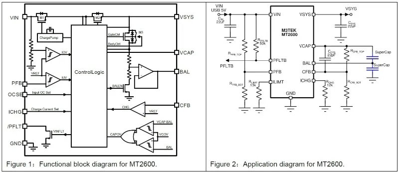
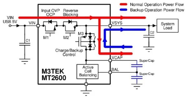
Figure 3: Operating diagram of Supercapacitor backup power system with MT2600.
Figure 3 shows the power flow path during normal operation mode and backup operation mode. When input power is available, system load is powered from input source. At the same time, supercapacitor is charged by input power with controlled current level and voltage level. When input power is lost, MT2600 will transition into backup operation mode automatically. It will also generate a fault signal PFLTB to inform system about the input power failure. In backup operation mode, power is supplied from supercapacitor.
Input Over Voltage/ Current Protection-HV Load Switch (M1)
In any system the capacitor is initially discharged. When the supply voltage is applied, the supercapacitor looks like a low value resistor. This can result in a huge inrush current if the current is not controlled or limited which could cause damage to these parts. Therefore, typically circuit of this type also requires short-circuit, over-voltage and current flow protection to prevent damage to following system.
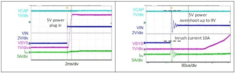
Figure 4 and 5: Load switch(M1) integrated input over voltage/current protection for MT2600.
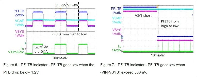
MT2600 integrated a programmable Input voltage monitor. When input voltage drops below certain voltage set by resistor divider connected to PFB pin. A flag signal on PFLTB will inform the following system about the event so that preventative actions can be taken like process and save data in DRAM.
Reverse Blocking Protection Ideal Diode (M2)
It also integrated an ideal diode for reverse blocking protection when input voltage is lost. The voltage difference VIN VSYS between the VIN and VSYS port is monitored continuously. Once the VIN VSYS 25mV the device immediately turns off the power switch to prevent the current flowing going back to the source and to protect the source during a short circuit.
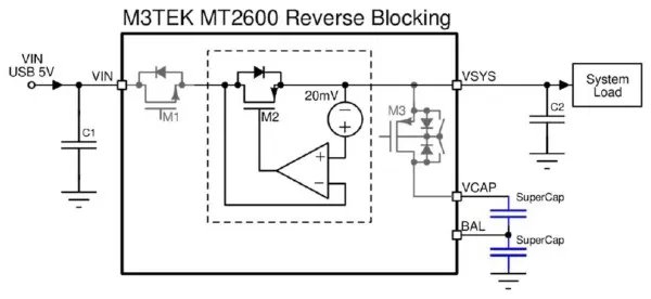
Figure 8: Reverse blocking protection circuit for MT2600.
Liner Charge Circuit (M3)
MT2600 integrated a linear charger to charge super capacitor with as high as 350mA current to achieve fast and safe charging. It includes trickle charge (TC), constant-current (CC)and constant-voltage (CV) charge. For deeply discharged capacitor, MT2600 uses TC charge to pre-condition the capacitor with a low current level that is typically half of the CC current. When VCAP rises above 1.08V, MT2600 start CC charge with the charging current programmed by external resistor on ICHG pin: RICHG = (KICHG)/(IICHG) = (3.6A∗kΩ)/(IILIM), such that its voltage is linearly increasing. As super-capacitors is charged to a target voltage which can be programed with VCAP feedback circuit: VCAP = [(RCFB_Top + RCFB_Bot)∗1.1V]/(RCFB_Bot), at which time the constant voltage loop becomes active and accurately controls the supercapacitor charge level to be constant to avoid over charging. Once the CFB voltage is above 1.1V, it will terminate the charging and set the End-of-Charge (EOC) state.
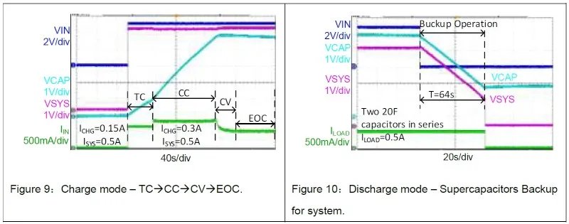
The charging devices also act as power path control switch. When input power is lost, this switch(M3) can be turned on without interruption to provide power to system rail with low resistance path up to 2A current in Backup Mode. In backup mode, quiescent current draw from super capacitor is only 2µA. This ensures very long standby time of the system with low capacitance super capacitor.
Operation Mode
The system should have three states: Standby State, Charge State, Discharge State and UVLO State as shown in Figure 11.
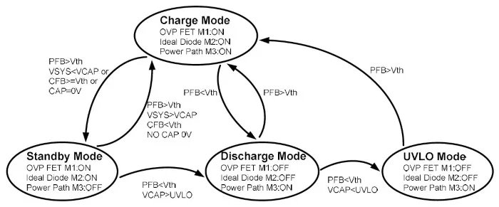
Figure 11: Charge mode, standby mode, discharge mode, UVLO mode interconvert condition.
Standby State
• VCAP VSYS, VIN is still available and PFB higher than threshold voltage. Or,
• VCAP reaches setting point by CFB and VIN is still available and PFB higher than threshold. Or,
• Any of the two super capacitor voltage reaches internal protection point and VIN is still available.
In Standby State, M3 FET should be kept OFF. M3 body diode need to be switches according to VSYS-VCAP voltage.
Charge State
VSYS VCAP, VIN is available and healthy; VCAP is below setting point by CFB. Both super capacitors are below over voltage protection point. In this state, we will turn of M3 with current limit set by ICHG.
Two possible features need to be evaluated:
• Input DPPM. If input voltage drops and PFB voltage drops close to set point, we can fold back charge current to limit current drain from weak input source.
• Soft charging ending. When VCAP is charged and CFB voltage getting close to set point, we can fold back charge current so that when charge stops, voltage drop on any impedance in series with capacitor doesn’t cause oscillation between charge mode/standby mode.
Discharge State
When PFB is below threshold, we consider input power source is gone. In this case, OVP FET is turned off. Ideal diode should be turned off too. Power path control FET M3 is turned on to connect VCAP to VSYS. Transition from Charge Mode or Standby Mode to Discharge Mode need to be smooth without huge inrush current, at the same time, it cannot let VSYS drop too much which might cause downstream system to shut down.
In Discharge mode, all the bias current is supplied by VCAP. To extend operating time, quiescent current need to be below 2uA in this case. Circuits need to be alive are:
• M3 over current detection circuit.
• UVLO detection circuit for VCAP.
UVLO State
In case the system runs on Super Capacitor for long time without recharge, eventually VCAP will drop too low to sustain the function of the whole system When VCAP drops too low, we will enter UVLO state. In this state, all the circuit is shut down. This state can only be cleared if VIN is supplied.
Active Voltage Balancing
When supercapacitors are used in a series configuration to achieve higher voltages, voltage balancing becomes an issue. Since individual devices can have capacitance variations of ±20%, the overall variation can be as much as 40% from one capacitor to another and the higher capacitance devices will experience greater voltage stress, resulting in reduced operating lifetimes or even damage them. Both passive and active approaches are used for cell balancing.
Series supercapacitors which use voltage-dividing resistors in parallel with each supercapacitor to balance the voltage are used in passive voltage balancing. It is the simplest and lowest-cost solution which will result in power loss in your circuit. It generally recommended only for applications where supercapacitors are infrequently charged and discharged due to its ineffective. For example, RBAL=1kΩ,power consumption through resistances is 3.5mW in case of 2.65V impressed to supercapacitor.
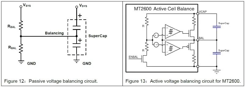
Active voltage balancing circuits control the voltages at the nodes of series connected devices, forcing them to be equal to a fixed reference voltage. MT2600 also integrated active voltage balancing with VMID pin connect to center point of two capacitors and protection circuit.
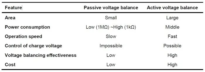
Table 2: Comparison of passive and active voltage balancing.
During charging mode, voltage between two stack capacitor (VMID pin) is compared with half of total capacitor voltage. Current is diverted to keep these two voltages close to each other. This circuit monitors voltage for each capacitor. During charging mode, if any capacitor voltage reaches 2.65V, charging will be stopped and recovery charging once the capacitor under 2.65V with cell balance be enabled through reducing about max. 3mA charge current for the cap to balance two-connected super-capacitors. Same way, during discharge mode, if any of the capacitor voltage drop below ground, discharging will be stopped to protect the capacitors. While active voltage is more complex, it tends to be more efficient and more accurate.
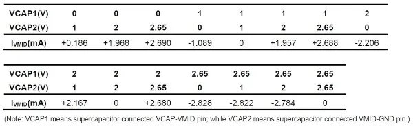
Table 3: Active voltage balancing operation test data during charge mode for MT2600.
Input Current Limit and Short Circuit Protection
For current limited adaptors or power sources, users can program the input current limit level to prevent the load current overload the source for charger mode. The MT2600 input current limit is set with an external resistor RILIMT connected between ILIMT and GND. If over-load occurs, the internal circuitry limits the input current based on the value of RILIM and pulls PFLTB pin LOW to report the fault condition. The current limit resistor RILIMT is selected through the equation: RILIM = KILIM/IILIM = 30A∗kΩ/IILIM.
The common current limit threshold setting is shown in the table:
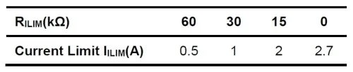
Table 4: Input current Limit setting by an external resistor RILIM.
The MT2600 also integrates a fast-trip comparator to quickly turn off the power switch when the output voltage is shorted to ground. The device operates hiccup mode in short circuit protection in charge mode. Once the short circuit fault is detected, the power switch is turned off and PFLTB from high to low as shown in Figure 7. At the end of the predetermined, a restart attempt is made by soft-starting the power switch. If the over-load condition has been removed, the power switch will turn on and operate normally; otherwise, the device will see another over-current event and shut off the power switch again, repeating the previous cycle.
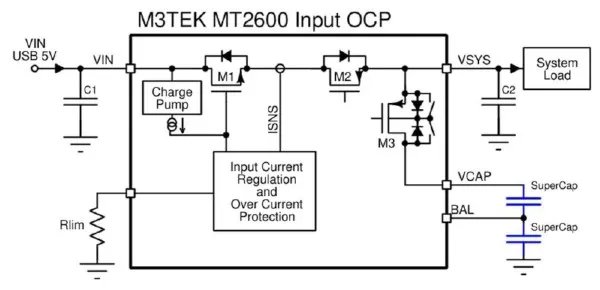
Figure 14: Charge mode VSYS short protection circuit for MT2600.
The excess heat due to overload lasts for only a short duration in the hiccup cycle, hence the junction temperature of the power devices is much lower. For example: 5Vin, hiccup mode current 2.5A, hiccup mode on time 160µs, off time 8ms, the average power loss only: 5V∗2.2A∗(160µs/8ms) = 0.22W.
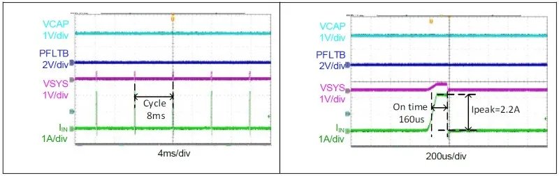
Figure 15 and 16: Charge mode VSYS short protection waveform.
Conclusion
Supercapacitor is showing great potential for applications with harsh operating environment, high storage energy need, high instant power capability, long standby time and maintains free deployment. Although engineers can implement supercapacitor charging circuits with conventional switched converters, a reliable and flexible power management IC with monitoring and protection features is needed to maximize supercapacitor efficiency and lifetime.
A fully integrated power management solution for system with two cell supercapacitors backup power applications is given by M3TEK’s MT2600. It provides programmable over current protection, input power failure, supercapacitor charge voltage configuration. MT2600 also integrated input power source over voltage protection to protect the system from input surge. With input power source reverse blocking circuit, it will protect the supercapacitor from discharging by input terminal. In backup mode when system draw power from supercapacitor, MT2600 only draws 2µA current from supercapacitor. This ensures long standby time in systems which need operate for days or even weeks with low power circuitry like real time clock or monitoring functions. This is a remarkably impressive tendency to using available supercapacitor charge ICs with adding supercapacitors to energy-harvesting designs for engineers.
Reference
“MT2600 Supercapacitor Power Manager for Backup Power System” M3TEK Datasheet.About the Author
Amin Hu is senior application engineer for the AE Department at M3Tek.
Bo Yang, Ph.D., is the director of the AE Department at M3Tek.
Nuo Lou is an R D manager at M3Tek.